 |
Frequency Programming By David Osborn - GD4HOZ |
|
|
The Synthesiser |
||
|
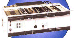
The FX5000 uses the GEC/Plessey NJ8820 synthesiser IC. This device has the means to interface to a PROM or EPROM to retrieve frequency data stored therein. The frequency data takes the form of 8 consecutive bytes which, between them, supply the values for 3 variables known as 'R', 'A' and 'M'. These values are written into internal registers to control the counters which do the work of frequency division. The 'R' counter divides the external reference frequency down to a value which is usually half the channel spacing (e.g. 6.25KHz for a 12.5KHz channel). Notice, though, that the Reference counter is followed by a fixed, divide-by-two, counter. Because of this, our calculations will focus on dividing the reference oscillator by a value of 'R' which results in a frequency equal to the channel spacing. The 'M' and 'A' counters perform the task of dividing the external VCO frequency. Since the division of the VCO frequency down to, say, 6.25KHz cannot always be achieved using an even number as a divisor, the 'A' register controls a switchable prescaler which, in the case of the receiver, alters the prescale factor from 80 to 81 by means of the Modulus Control output. More on this topic follows. |
||
|
NJ8820 Data Format |
||||||||||||||||||||||||||||||||||||||||||||||||||||||||||||||||||||||||||||||||||||||||||||||||||||||||||||||||||||||||||||||||||||||||||||||||||||||
The table shows how the bits making up the values of R, A and M are split up between the 8 data bytes required by the synthesiser when stored in an EPROM. Most notable is the fact that the bits making up the M value are left-shifted by two bits. |
||||||||||||||||||||||||||||||||||||||||||||||||||||||||||||||||||||||||||||||||||||||||||||||||||||||||||||||||||||||||||||||||||||||||||||||||||||||
|
FX5000 notes to bear in mind |
||||||||||||||||||||||||||||||||||||||||||||||||||||||||||||||||||||||||||||||||||||||||||||||||||||||||||||||||||||||||||||||||||||||||||||||||||||||
|
General Notes:
The EPROM data is split up into two types: Normal (customer data) and test data. Each of these groups is further split into transmit and receive frequency data. This gives rise to four groups of frequency data, viz:
Mysteriously, the existing EPROM in my FX5000 has no data in the locations that would be appropriate for channel zero. I didn't attempt to reason this out, and simply followed the pattern. Therefore, the first channel data values begin at 0x0008 for the transmitter, and 0x0408 for the receiver (8 bytes per channel, remember).
|
||||||||||||||||||||||||||||||||||||||||||||||||||||||||||||||||||||||||||||||||||||||||||||||||||||||||||||||||||||||||||||||||||||||||||||||||||||||
|
Transmitter |
Receiver |
|||||||||||||||||||||||||||||||||||||||||||||||||||||||||||||||||||||||||||||||||||||||||||||||||||||||||||||||||||||||||||||||||||||||||||||||||||||
|
|
|
|||||||||||||||||||||||||||||||||||||||||||||||||||||||||||||||||||||||||||||||||||||||||||||||||||||||||||||||||||||||||||||||||||||||||||||||||||||
|
Worked Example |
||||||||||||||||||||||||||||||||||||||||||||||||||||||||||||||||||||||||||||||||||||||||||||||||||||||||||||||||||||||||||||||||||||||||||||||||||||||
|
Transmitter Calculations |
Receiver Calculations |
|||||||||||||||||||||||||||||||||||||||||||||||||||||||||||||||||||||||||||||||||||||||||||||||||||||||||||||||||||||||||||||||||||||||||||||||||||||
|
Let the desired TX frequency be 145.6250MHz (GB3GD): Calculate the value of 'R' - the divisor for the reference oscillator. We are looking for a result which is equal to the value of the channel spacing (12.5KHz in our case). The reference divider is followed by a fixed divide by 2, yielding the final desired result of half the channel spacing. R = Fref / Channel Spacing Next we calculate an intermediate value 'N'. This is the value by which the input sample frequency must be divided in order to get a frequency equal to half the channel spacing. N = (Ftx + 20) / 6.25KHz N=(145.625MHz + 20) / 6.25KHz Using 'N', Calculate 'M' and 'A': M=N / TX Prescaler M=26500 / 64 = 414 with a remainder of 4 So: M = 414, and A = 4 We now have R, A and M. These are the three values required by the NJ8820. R=0x064, A=0x04, M=0x19E These values have to be arranged in accordance with the data format chart shown above. Note in particular that the lower two bits of the first byte are not used and that the data for 'M' has to be shifted to the left.
|
Let the desired RX frequency be 145.0250MHz (GB3GD): Calculate 'R': R=Fref / Channel Spacing Calculate 'N': N=(Frx-21.4) / Fr Using 'N', Calculate 'M' and 'A': M=N / RX Prescaler So: M = 247 and A = 20 Expressed in Hexadecimal: R=0x2A0, A=0x14, M=0x0F7 With the receiver values we have to be cautious because of the need to "flip" each four-bit nibble around. Let's do that, beginning with 'R': R = 0x2A0 2 in binary = 0010, "Flipped", it becomes 0100 A = 0x14 1 = 0001, becomes 1000 M=0xF7 F = 1111, remains the same These new values are the ones which are "plugged-in" to the table. |
|||||||||||||||||||||||||||||||||||||||||||||||||||||||||||||||||||||||||||||||||||||||||||||||||||||||||||||||||||||||||||||||||||||||||||||||||||||
| NJ8820 Data Format | Sample Data | |||||||||||||||||||||||||||||||||||||||||||||||||||||||||||||||||||||||||||||||||||||||||||||||||||||||||||||||||||||||||||||||||||||||||||||||||||||
|
|
|||||||||||||||||||||||||||||||||||||||||||||||||||||||||||||||||||||||||||||||||||||||||||||||||||||||||||||||||||||||||||||||||||||||||||||||||||||
|
And that's how it's done. Easy isn't it? Make a spreadsheet do the work I have concocted an Excel Workbook which does all of the hard work for you. Since it uses certain features which are not included "out of the box", you may need your Excel installation disk in order to add the appropriate plug-ins. I would stress, however, that I make no claims to perfection. I have only used the data for 145.625MHz TX and 145.025MHz RX in my particular application. These values work perfectly and so I can see no reason why the others should not, but...... |
||||||||||||||||||||||||||||||||||||||||||||||||||||||||||||||||||||||||||||||||||||||||||||||||||||||||||||||||||||||||||||||||||||||||||||||||||||||
